InfraredHeaters.com Questions? 1-800-442-2581 |
Our secure online
ordering website: www.MorElectricHeating.com.
|
|
| Home | Products | Accessories | Ordering | Contact Us | Search | ||
InfraredHeaters.com Questions? 1-800-442-2581 |
Our secure online
ordering website: www.MorElectricHeating.com.
|
|
| Home | Products | Accessories | Ordering | Contact Us | Search | ||
Salamander Ceramic Infrared Emitters Technical Manual Page 5
Ceramic Infrared Panel Design
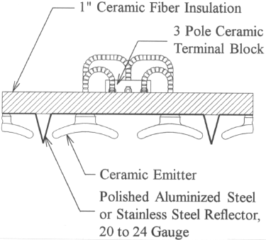
Typical Panel Configuration

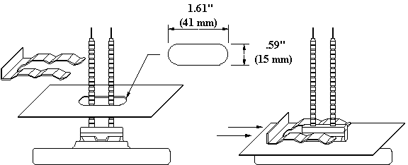
Ceramic Emitter Mounting

This drawing shows a ceramic heater and a reflector
with an oblong hole for mounting.
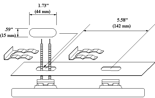
LTE Ceramic Emitter Mounting

Our larger LTE element has two mounting posts on the
back side. This drawing shows an LTE and a reflector with two oblong holes for mounting.

This drawing shows an LTE installed in a reflector.
|
|
High
temperature 842°F (450°C) MG or similar style wire (with a suitable temperature and
amperage rating) should be used for all electrical connections made within the terminal
area of the infrared panel. The high temperature wire must be run on top of (or above) the
ceramic fiber insulation. |
|
|
Ceramic terminal blocks are
recommended to allow for quick emitter replacement, flexibility in zoning, and "touch safe" design. |
|
|
The terminal cover for the infrared panel should be louvered or made out of expanded metal to minimize the temperature within the terminal area. |
The spacing of the emitters should be such that the resulting infrared emissions incident on the target will be even and maximized.
|
|
Emitters that are tightly spaced in an array will allow the
target to be positioned close to the emitters and still result in even heating. The
intensity and efficiency of the infrared radiation will be maximized and heat losses will
be minimized. |
|
|
Emitters that are loosely spaced in an array will force the target to be positioned further away in order to achieve even heating. This style of panel would typically result in a lower intensity infrared emission. |
For more information about emitter mounting, using our two piece mounting clip design and warnings see our emitter mounting page.
 Page 4
Page
6
Technical Manual Table of Contents
![]() Technical Manual in Acrobat .pdf format
Technical Manual in Acrobat .pdf format
|
We are a distributor of infrared heaters. Always consult manufacturers installation instructions for proper installation of the products or systems shown on this website. © Copyright 1999-2019 Mor Electric Heating Assoc., Inc. MOR
ELECTRIC HEATING ASSOC., INC. |